Since each port on the main show controller is limited to 800 total pixels and to accommodate a large expansion of pixels (25,000 on order) more remotes are required along with a second controller. So, I’m building three Genius PRO 8 port receivers and one Genius PRO 16 port controller.
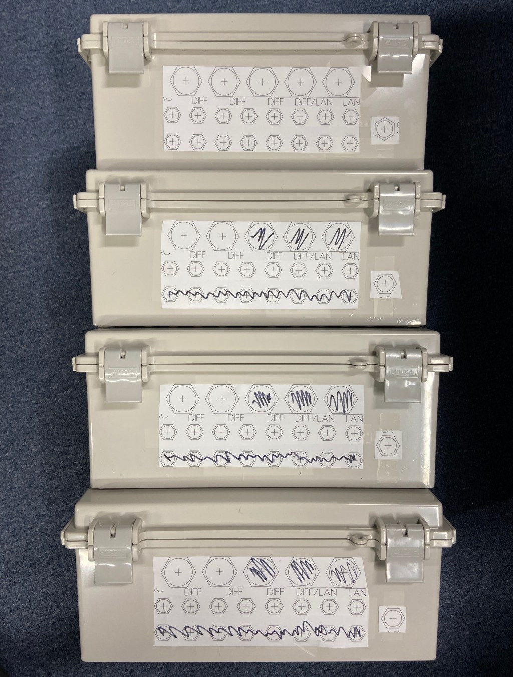
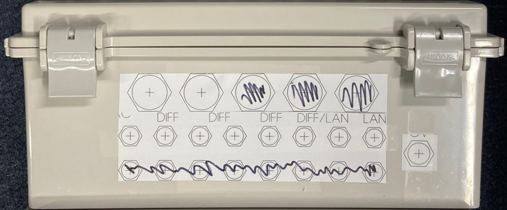
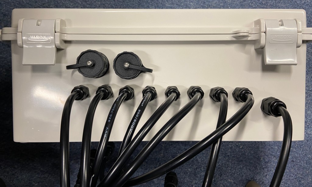
I’m using a BUD industries NBF-32022 box for all four builds. I start with a template taped to the side to neatly drill the 5/8” power cord hole, 8 or 16 depending on the board ½” port holes, and 2 or 3 1” holes for the networking glands. The way I space things out leaves room for future modification in case I want to convert it to a 16 port or a controller. *TIP – use a step bit for clean holes as the BUD box tends to melt and stick to bits under high friction*
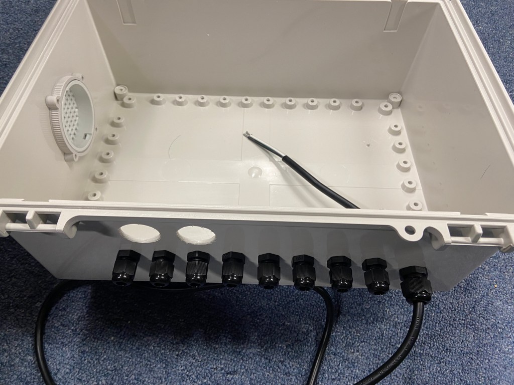
I then add the port glands which are size PG7 as well as a single PG9 gland for the power cable. I cut a 2½” hole on the side and add an IPV-1115 air vent.
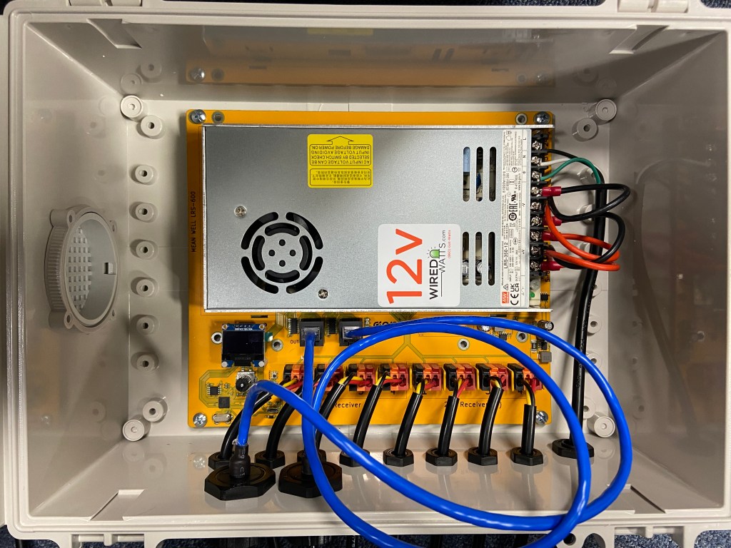
The thing I love the most about the Genius PRO series of controllers and remotes is that the circuit board itself is the mounting plate. I mount the Meanwell LRS-350-12 12v 350w power supply directly to the board, attach the positive and negative leads, then screw the board into the BUD box. *TIP – be sure to update the firmware on the board before installing or attaching to the power supply*
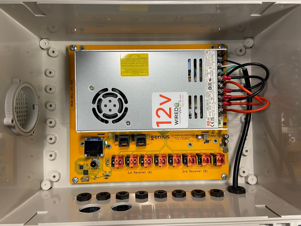
The most tedious part is installing all of the port leads. I use 18” xConnect leads. Round is best to have a waterproof seal in the glands. The red (voltage), yellow (data), and black (neutral) ends come pre-tinned with solder. The Genius boards now use lever locks, so it’s nice and simple to pull the lever back, drop the cord in, and lock the lever. *TIP – cut off the tinned tips, strip, and insert bare strands for the most secure connection on the lever locks* Lastly, I add the 2 network port glands (3 for the controller) and it’s all done!

Leave a reply to listjoejr75 Cancel reply